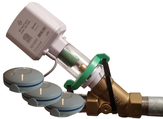
The offline leakage protection system 'KFRFLO' detects water leaks using multiple water sensors distributed throughout the house and shuts off the water supply in the event of a leak. The unique feature of this system is that it does not require an app, internet, or Wi-Fi.
The retrofit motor is installed in place of the handwheel on the main shut-off valve. The product bundle includes three battery-operated water sensors that are paired with the motor and distributed around the house.
Communication between the sensors and the motor uses the highly reliable, standardized LoRa wireless technology, specifically designed for such applications. No additional equipment like a gateway is needed. All sensors communicate directly with the motor in case of an alarm, making the system installation very straightforward.
In the event of an alarm, the affected sensor emits a loud audible signal and flashes red. The motor shuts off the water, also emitting an audible signal and flashing red. The alarm can be cleared, and the water turned back on by pressing the button on the motor.
 |
 |
 |
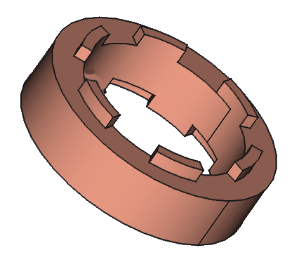 |
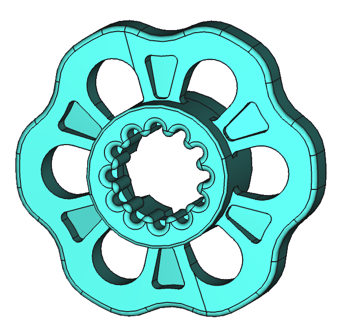
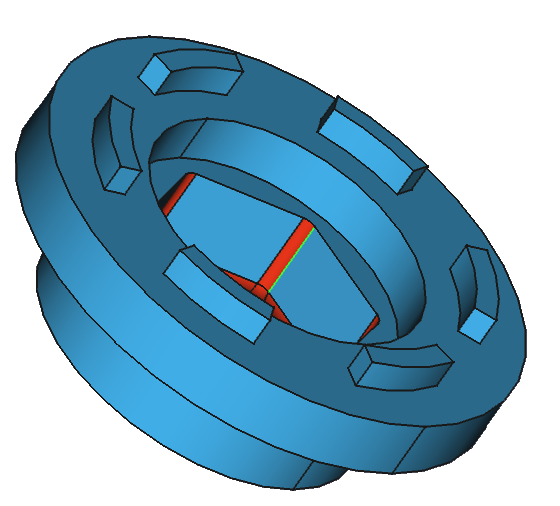
| Handwheel (H) | Inner Coupling (K) | Adapter (Ax) | Distance Rings (D1,D2) |
 |
 |
 |
 |
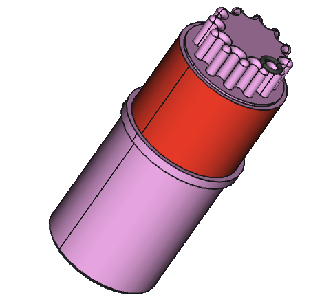
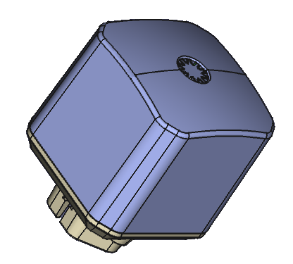
| Ball Bearing Seat (Ws) | Motor (M) | Main Body (G) | Bracket (N) |
The motorized actuator can be used with all commercially available angle seat valves. However, due to the variety of mechanics, certain adaptations must be made. For installation, leave the valve open or rotate it to the open position. Plumbers recommend that the valve is fully opened first and then lightly closed by turning it clockwise approximately 2 turns.

Each time the motor is disconnected from power, it will determine its current position. It briefly moves in the 'Close' direction. If this is not possible, the motor defines the current position as the 'Open' position. The next 'Close' command will fully close the valve. On the following 'Open' command, the motor will move to the previously defined 'Open' position. This allows you to set the 'Open' position of the valve yourself by only opening the valve as far as necessary and then reconnecting the power, making this self-chosen position the 'Open' position.
If the motor detects a closed valve when power is connected, it will open to the valve's full-open position on the next opening command and then close it back by two turns, as currently recommended by plumbing professionals. The factory setting allows a maximum of 10 turns between 'Open' and 'Close.' This value can be adjusted if necessary via configuration parameter 9.
The product is supplied with a portion of epoxy. This is a two-part mixture. Mix the two components by kneading until the mass has a similar color. Select an adapter ring that just fits over the base structure of the valve bonnet and fill the gaps with the prepared epoxy. Allow the epoxy to cure. Note that the epoxy will adhere to the metal body. If you do not want the epoxy to stick, coat the metal body with some oil to allow easy removal of the epoxy filled adapter.
In the same way, you can put epoxy in one of the bearing seats if your stem is smaller than the is smaller than the 6x6mm of the smallest seat. Make sure the stem is positioned right in the centre of the ball bearing seat.
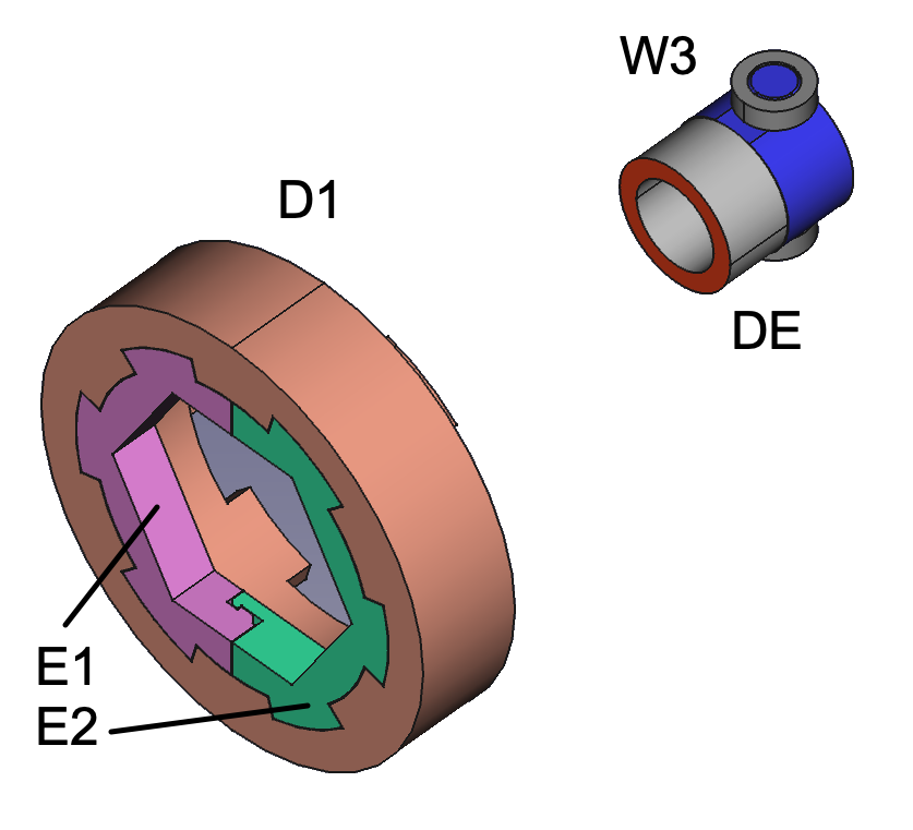 This company's valves have a very special design. You must insert the split ring (E1+E2)
into the 24 mm distance ring (D1) instead of using one of the adapters A1 ... A4. No
further distance ring is needed but a small ring DE must be placed below the ball bearing
seat to hold down the large fat chamber.
This company's valves have a very special design. You must insert the split ring (E1+E2)
into the 24 mm distance ring (D1) instead of using one of the adapters A1 ... A4. No
further distance ring is needed but a small ring DE must be placed below the ball bearing
seat to hold down the large fat chamber.
The unit allows an optional wired flood sensor to be attached. There is a connector on the power cord next to the motor. Remove the blue protective pad and plug in the sensor. Please use some force to push the connector to ensure a waterproof connection. If the sensor head detects water, a flood alarm will sound, the valve will close, and the alarm will be indicated by a buzzer and LEDs. Once the sensor head is free of water, you can clear the alarm by pressing the button for 2 seconds. It is also possible to clear the alarm with a wireless LORA command. In both cases, an Alarm Clear report is sent uplink to the LORA network.
You can open or close the valve by briefly pressing the button. If you press the button while the motor is running, the motor stops moving and will reverse direction with next push.
The unit must be calibrated to recognize the end positions of the valve. Once these end positions are known, the motor will stop softly at that position and not "slam into the wall" to protect the mechanics and ensure long life and reliable operation. After power up, the unit will make some short movements to determine if the last position was open or close. The first open or close operation is used to perform calibration for both end points. No special user interaction is required for calibration.
The unit has a two-color LED with the following meaning
The system comes with three water sensors by default, but additional sensors (product code FLOLWE02) can be ordered from the Aqua-Scope shop.
The first step is to insert the CR123 battery. Turn the top of the sensor housing counterclockwise to open the housing. Inside you will see the functional components of the unit:
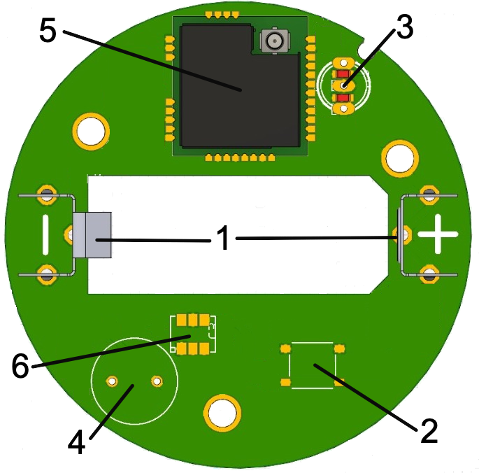
After inserting the battery (resp. removing the isolating slip), the device is ready for operation. You can check the function by hitting the button. You will hear a beep and the LED goes on
When water is detected an alarm packet is sent out, the LED turns red and the device continues beeping.
Close the housing by turning the top of the housing 1/8 turn clockwise.
The sensors can either be placed directly on the floor or mounted on the wall using the provided bracket. For wall mounting, the sensor cable needs to be plugged into the bracket, with the socket ideally pointing downwards.
Should you encounter any problem, please give us the opportunity to address it before returning this product. Please check our website www.aqua-scope.com and particularly the support section for answers and help. You can also send a message to info@aqua-scope.com.
While the information in this manual has been compiled with great care, it may not be deemed an assurance of product characteristics. Aqua-Scope shall be liable only to the degree specified in the terms of sale and delivery. The reproduction and distribution of the documentation and software supplied with this product and the use of its contents is subject to written authorization from Aqua-Scope. We reserve the right to make any alterations that arise as the result of technical development.
 Aqua-Scope Technology OÜ, Sakala 7-2, 10141 Tallinn, Republic of Estonia, declares that
this radio emitting device works on the following frequences:
Aqua-Scope Technology OÜ, Sakala 7-2, 10141 Tallinn, Republic of Estonia, declares that
this radio emitting device works on the following frequences:
Български С настоящото Aqua-Scope Technology OÜ декларира, че този тип радиосъоръжение KFRFLO01 е в съответств ие с Директива 2014/53/ЕС. Цялостният текст на ЕС декларацията за съответствие може да се намери н а следния интернет адрес: www.aqua-scope.com/ce.
Čeština Tímto Aqua-Scope Technology OÜ prohlašuje, že typ rádiového zařízení KFRFLO01 je v souladu se směrnicí 2014/53/EU. Úplné znění EU prohlášení o shodě je k dispozici na této internetové adrese: www.aqua-scope.com/ce.
Dansk Hermed erklærer Aqua-Scope Technology OÜ, at radioudstyrstypen KFRFLO01 er i overensstemmelse med direktiv 2014/53/EU. EUoverensstemmelseserklæringens fulde tekst kan findes p følgende internetadresse: www.aqua-scope.com/ce.
Deutsch Hiermit erklärt Aqua-Scope Technology OÜ, dass der Funkanlagentyp KFRFLO01 der Richtlinie 2014/53/EU entspricht. Der vollständige Text der EU-Konformitätserklärung ist unter der folgenden Internetadresse verfügbar: www.aqua-scope.com/ce.
Eesti Käesolevaga deklareerib Aqua-Scope Technology OÜ, et kesolev raadioseadme tp KFRFLO01 vastab direktiivi 2014/53/EL nuetele. ELi vastavusdeklaratsiooni tielik tekst on kttesaadav jrgmisel internetiaadressil: www.aqua-scope.com/ce
English Hereby, Aqua-Scope Technology OÜ declares that the radio equipment type KFRFLO01 is in compliance with Directive 2014/53/EU. The full text of the EU declaration of conformity is available at the following internet address: www.aqua-scope.com/ce
Español Por la presente, Aqua-Scope Technology OÜ declara que el tipo de equipo radioeléctrico KFRFLO01 es conforme con la Directiva 2014/53/UE. El texto completo de la declaracin UE de conformidad está disponible en la direccin Internet siguiente: www.aqua-scope.com/ce
Ελληνικά Με την παρούσα ο/η Aqua-Scope Technology OÜ, δηλώνει ότι ο ραδιοεξοπλισμός KFRFLO01 πληροί την οδηγία 2014/53/ΕΕ. Το πλήρες κείμενο της δήλωσης συμμόρ φωσης ΕΕ διατίθεται στην ακόλουθη ιστοσελίδα στο διαδίκτυο: www.aqua-scope.com/ce
Français Le soussigné, Aqua-Scope Technology OÜ, déclare que l'équipement radioélectrique du type KFRFLO01 est conforme la directive 2014/53/UE. Le texte complet de la déclaration UE de conformité est disponible l'adresse internet suivante: www.aqua-scope.com/ce
Hrvatski Aqua-Scope Technology OÜ ovime izjavljuje da je radijska oprema tipa KFRFLO01 u skladu s Direktivom 2014/53/EU. Cjeloviti tekst EU izjave o sukladnosti dostupan je na sljedećoj internetskoj adresi: www.aqua-scope.com/ce
Italiano Il fabbricante, Aqua-Scope Technology OÜ, dichiara che il tipo di apparecchiatura radio KFRFLO01 conforme alla direttiva 2014/53/UE. Il testo completo della dichiarazione di conformit UE disponibile al seguente indirizzo Internet: www.aqua-scope.com/ce
Latviešu Ar šo Aqua-Scope Technology OÜ deklarē, ka radioiekārta KFRFLO01 atbilst Direktīvai 2014/53/ES. Pilns ES atbilstības deklarācijas teksts ir pieejams šādā interneta v ietnē: www.aqua-scope.com/ce Lietuvių Aš, Aqua-Scope Technology OÜ, patvirtinu, kad radijo įrenginių tipas KFRFLO01 atitinka Direktyvą 2014/53/ES. Visas ES atitikties deklaracijos tekstas prieinamas šiuo internet adresu: www.aqua-scope.com/ce
Magyar Aqua-Scope Technology OÜ igazolja, hogy a KFRFLO01 típus rádiberendezés megfelel a 2014/53/EU irányelvnek. Az EUmegfelelőségi nyilatkozat teljes szövege elérhető a következő internetes címen: www.aqua-scope.com/ce
Malti B'dan, Aqua-Scope Technology OÜ, niddikjara li dan it-tip ta' tagħmir tar-radju KFRFLO01 huwa konformi madDirettiva 2014/53/UE. It-test kollu tad-dikjarazzjoni ta' konformit tal-UE huwa disponibbli f'dan l-indirizz talInternet li ġej: www.aqua-scope.com/ce
Nederlands Hierbij verklaar ik, Aqua-Scope Technology OÜ, dat het type radioapparatuur KFRFLO01 conform is met Richtlijn 2014/53/EU. De volledige tekst van de EUconformiteitsverklaring kan worden geraadpleegd op het volgende internetadres: www.aqua-scope.com/ce
Polski Aqua-Scope Technology OÜ niniejszym oświadcza, że typ urządzenia radiowego KFRFLO01 jest zgodny z dyrektywą 2014/53/UE. Pełny tekst deklaracji zgodnośc I UE jest dostępny pod następującym adre sem internetowym: www.aqua-scope.com/ce
Português O(a) abaixo assinado(a) Aqua-Scope Technology OÜ declara que o presente tipo de equipamento de rádio KFRFLO01 está em conformidade com a Diretiva 2014/53/UE. O texto integral da declarao de conformidade está disponível no seguinte endereo de Internet: www.aqua-scope.com/ce
Română Prin prezenta Aqua-Scope Technology OÜ declară că tipul de echipamente KFRFLO01 este în conformitate cu Directiva 2014/53/UE. Textul integral al declarației UE de conformitate este disponibil la următoarea adresă internet: www.aqua-scope.com/ce
Slovensko Aqua-Scope Technology OÜ potrjuje, da je tip radijske opreme KFRFLO01 skladen z irektivo 2014/53/EU. Celotno besedilo izjave EU o skladnosti je na voljo na naslednjem spletnem naslovu: www.aqua-scope.com/ce
Slovensky Aqua-Scope Technology OÜ týmto vyhlasuje, že rádiové zariadenie typu KFRFLO01 je v slade so smernicou 2014/53/EÚ. Úplné EÚ vyhlásenie o zhode je k dispozícii na tejto internetovej adrese: www.aqua-scope.com/ce
Soumi Aqua-Scope Technology OÜ vakuuttaa, että radiolaitetyyppi KFRFLO01 on direktiivin 2014/53/EU mukainen. EUvaatimustenmukaisuusvakuutuksen täysimittainen teksti on saatavilla seuraavassa internetosoitteessa: www.aqua-scope.com/ce
Svenska Härmed försäkrar Aqua-Scope Technology OÜ att denna typ av radioutrustning KFRFLO01 verensstmmer med direktiv 2014/53/EU. Den fullständiga texten till EUförsäkran om verensstämmelse finns på följande webbadress: www.aqua-scope.com/ce
 Do not dispose of electrical appliances as unsorted municipal waste, use separate collection
facilities. Contact your local government for information regarding the collection systems
available. If electrical appliances are disposed of in landfills or dumps, hazardous
substances can leak into the groundwater and get into the food chain, damaging health and well-being.
Do not dispose of electrical appliances as unsorted municipal waste, use separate collection
facilities. Contact your local government for information regarding the collection systems
available. If electrical appliances are disposed of in landfills or dumps, hazardous
substances can leak into the groundwater and get into the food chain, damaging health and well-being.