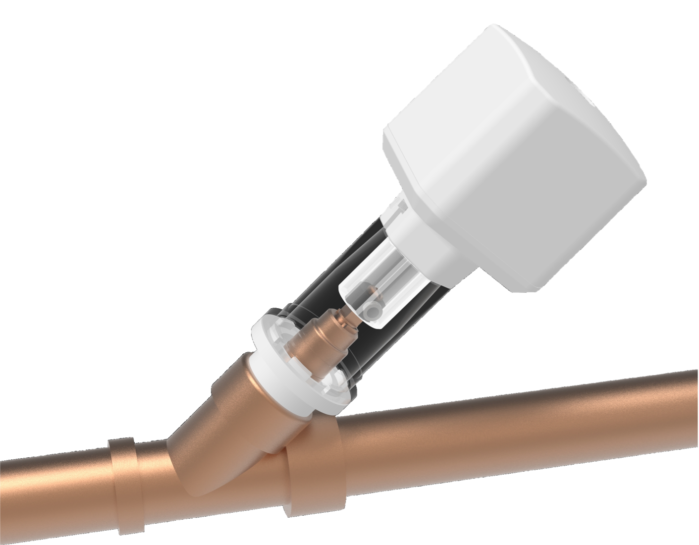
The motor drive for angle seat valves (KFR valves) enables the retrofitting of existing and already installed shut-off valves into remotely controllable smart devices, without interrupting the water supply or cutting into the water pipe.
The device supports the LoRaWAN wireless protocol and can be integrated into an existing LoRaWAN network as a Class C device. This requires LoRaWAN network coverage and that the device keys be registered with the LoRaWAN provider’s JOIN server. If no LoRaWAN connection is available, the device will automatically accept control commands from Aqua-Scope sensors after about 20 seconds. Details can be found in the section 'Communication with a LoRaWAN Network'.
The motor is powered by a 12V power supply and is fully water- and dirt-resistant up to the power supply unit. An optional battery pack is available for off-grid operation.
Various adapter rings and a sophisticated connection system allow the motor to be used with all modern angle seat valves from DN15 to DN32. Thanks to an additional water sensor that can be plugged directly into the device, the motor can also be used for leakage protection without any wireless connection at all.
 |
 |
 |
 |
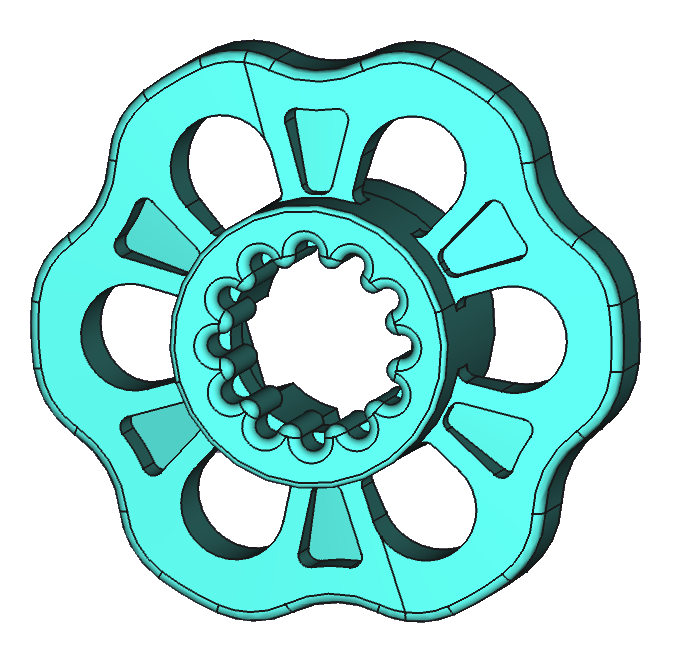
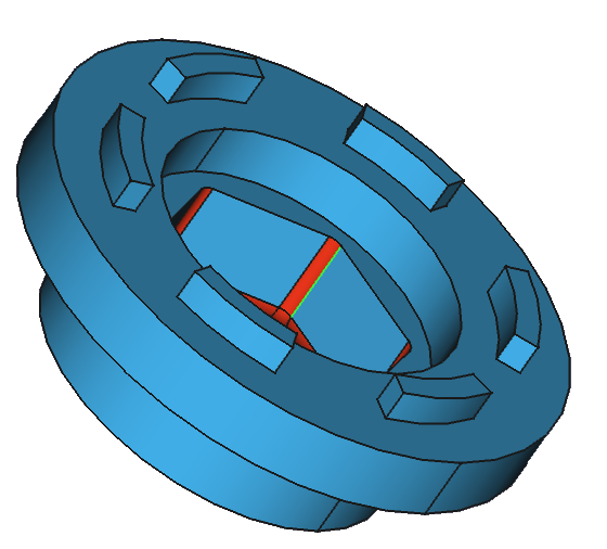
| Handwheel (H) | Inner Coupling (K) | Adapter (Ax) | Distance Rings (D1,D2) |
 |
 |
 |
 |
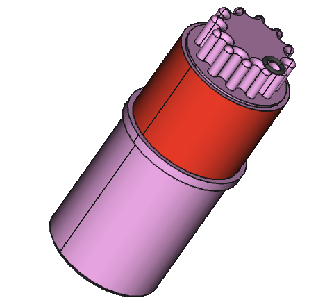
| Ball Bearing Seat (Ws) | Motor (M) | Main Body (G) | Bracket (N) |
The motor drive can be used with all commercially available angle seat valves. However, due to the variety of mechanisms, certain adjustments must be made. When installing, the valve should be normally open (installers recommend opening the valve fully and then closing it slightly with approx. 2 clockwise turns).

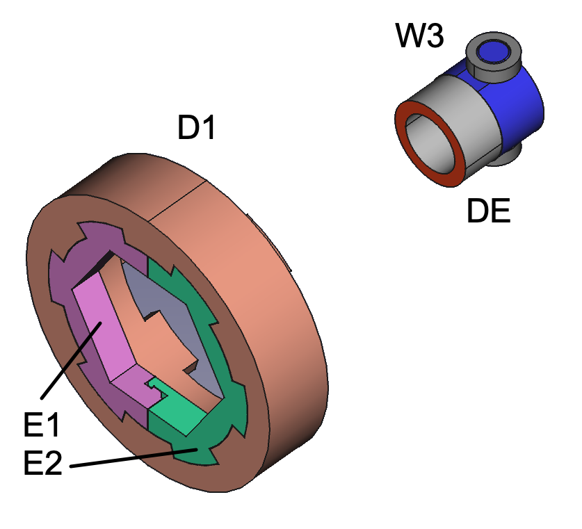
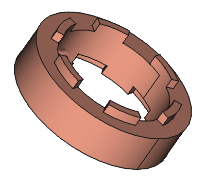
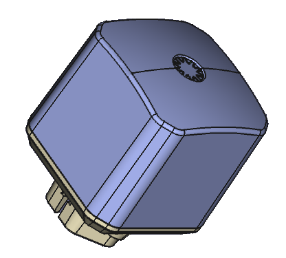
The valves from this company have a unique design. You must insert the split ring (E1+E2) into the 24 mm spacer ring (D1) instead of using one of the adapters A1 ... A4. A small additional spacer ring (DE) is placed directly under the ball bearing seat to fix the valve's grease chamber.
If no suitable adapter is available for the valve seat, a custom one must be made. To do this, select an adapter that fits over the valve seat and fill the gap with a two-component resin. This resin is included with the motor. Cut off a piece of the compound with a utility knife and knead it until a uniform color is achieved. Then fill the gaps between the adapter ring and the valve base. After the resin has hardened, the now custom-fit adapter ring can be used.
Note: The resin will adhere firmly to the valve. If this is not desired, lightly oil the valve beforehand. Then the hardened adapter ring can be removed more easily.
Similarly, a ball bearing seat can be adapted for a valve shaft with a square smaller than 6x6 mm. Ensure that the spindle is precisely centered in the ball bearing seat.
Once the motor is mounted and powered, it must determine the correct end positions for the ‘OPEN’ and ‘CLOSE’ positions:
Once the end positions are recognized, the motor will no longer forcefully drive against the valve's endpoints, but will instead count the required motor turns and approach the endpoints gently.
An optional wired flood sensor can be connected to the device. There is a plug on the power cable near the motor. Remove the blue rubber plug and insert the sensor. Please push the connector in firmly to ensure a waterproof connection.
If the sensor head detects water, an acoustic signal will sound, the valve will close, and the alarm will be indicated by a flashing red LED. In addition, an alarm message will be sent via LoRa radio. Once the sensor head is free of water, you can clear the alarm by pressing the button for 2 seconds. It is also possible to clear the alarm via radio.
The device has a single button with a built-in three-color LED. To operate the valve, you can either click the button or press and hold it for a few seconds. The motor helps count the seconds by beeping once per second. The device is designed for outdoor use and must prevent malfunctions caused by water drops on the button. Therefore, please press the button firmly (not too timidly), even for short clicks, so that the touchless button can detect your finger.
Using the button on the motor head (G), various commands can be sent to the motor:
The device has a two-color LED with the following meanings:
Please register the device with its three keys on your LoRaWAN server before putting it into operation. The device EUI is printed on the device. Enter this key and your registered email address at https://aqua-scope.com/lora to receive the remaining two keys. The email address is the account email from the Aqua-Scope shop, or the data will be provided by your vendor.
If there is no LoRaWAN network or the LoRa keys are not registered in the LoRa network, the LoRaWAN connection process will fail after about 25 seconds, and the device will automatically switch to LoRaP2P mode for direct control by Aqua-Scope sensors. Please note that the device will always attempt to connect to the LoRaWAN network after power is turned on.
LoRaWAN commands can be daisy chained into the payload up to the defined maximum payload size of 51 bytes. This mean that for all commands sent to defined number of bytes in the payload is required to avoid misinterpretation of command and/or command values in the receiver side. All uplink and downlink commands use FPort=10.
The following sensor types are supported by the Aqua-Scope Monitor.
The following alarmtypes are supported.
All Configuration Parameters are 2 Byte values that can be set and read out using LoRaWAN 'Configuration Get' and 'Configuration Set' commands. Here is an overview of the configuration parameters currently used:
This parameter defines how often (in minutes) a status report is sent out.
This parameter defines whether confirmed or unconfirmed messages are sent over LoRaWAN. 0x01 = confirmed message, value 0x00 unconfirmed message.
This parameter defines whether a temperature value should be in Celsius (0x00) or Fahrenheit (0x01).
This parameter defines how an alarm report is sent to the LoRa network. The parameter combines two different values: The more significant byte describes how often an alarm packet is retransmitted. The default setting here is 0x03 = 3 times. A value between 0x00 (no repetition) and 0xff (unlimited repetition) can be selected. The least significant byte defines the repeat interval in minutes.
A valve should be moved regularly to maintain its smooth operation. The device can perform this training independently from control by a LoRa network. The parameter combines two different values: The higher-order byte describes whether (1) or not (0) valve training should take place. The low-order byte defines the interval of the training in days. Values between 1 and 30 days are possible. The default value is 0x0107, i.e. training takes place every 7 days.
With this parameter the buzzer and the LEDs can be activated (0x01) or deactivated (0x00) directly at the device. The lower byte defines the behavior of the buzzer, the higher byte the behavior of the LED. The default value is 0x0101, i.e. both buzzer and LED are active (for example during motor movement).
This parameter defines at which temperature change an additional temperature report is sent in addition to the regular temperature report. The value is given in 0.1 degrees Celsius and must be greater than 0x000a (= 1 degree).
This parameter allows limiting the motors torque. Max torque is 0x64 = 100 percent. Valid values are 0x50 .. 0x64.
Set the total turns of the valve. This value is set by calibration but can be changed manually if desired.
In battery mode, the motor sleeps but wakes up frequently to receive commands. This parameter defines (in ms) how long the motor is in receive mode during the wakeup.
In battery mode, the motor sleeps but wakes up frequently to receive commands. This parameter defines (in seconds) how long the motor will sleep before waking up into receive mode. Setting the parameter to 0 turns off the low power mode and keeps the motor awake all the time.
In battery mode, the motor sleeps but wakes up frequently to receive commands. this parameter defines the number of receive-only wake ups, before a sync packet is sent upstream to resync the timers of the motor and the communicating device. Since parameter 13 defines the time between two receive-only wake ups, p13 * p14 defines the total time in seconds between two wakeup reports. Even if the communicating device does not support the low power mode, this period defines the longest waiting time before a command is finally received and executed.
This parameter defines if the direct pairing to sensors without involvement of an App is enabled. (1 = enabled, 0 = disabled)
0 = do it on first button resp. first wireless command, 1 = do it always on power on
turns back 1/x after hit close position
Should you encounter any problem, please give us the opportunity to address it before returning this product. Please check our website www.aqua-scope.com and particularly the support section for answers and help. You can also send a message to info@aqua-scope.com.
While the information in this manual has been compiled with great care, it may not be deemed an assurance of product characteristics. Aqua-Scope shall be liable only to the degree specified in the terms of sale and delivery. The reproduction and distribution of the documentation and software supplied with this product and the use of its contents is subject to written authorization from Aqua-Scope. We reserve the right to make any alterations that arise as the result of technical development.
 Aqua-Scope Technology OÜ, Sakala 7-2, 10141 Tallinn, Republic of Estonia, declares that
this radio emitting device works on the following frequences:
Aqua-Scope Technology OÜ, Sakala 7-2, 10141 Tallinn, Republic of Estonia, declares that
this radio emitting device works on the following frequences:
Български С настоящото Aqua-Scope Technology OÜ декларира, че този тип радиосъоръжение KFRLWE01 е в съответств ие с Директива 2014/53/ЕС. Цялостният текст на ЕС декларацията за съответствие може да се намери н а следния интернет адрес: www.aqua-scope.com/ce.
Čeština Tímto Aqua-Scope Technology OÜ prohlašuje, že typ rádiového zařízení KFRLWE01 je v souladu se směrnicí 2014/53/EU. Úplné znění EU prohlášení o shodě je k dispozici na této internetové adrese: www.aqua-scope.com/ce.
Dansk Hermed erklærer Aqua-Scope Technology OÜ, at radioudstyrstypen KFRLWE01 er i overensstemmelse med direktiv 2014/53/EU. EUoverensstemmelseserklæringens fulde tekst kan findes p følgende internetadresse: www.aqua-scope.com/ce.
Deutsch Hiermit erklärt Aqua-Scope Technology OÜ, dass der Funkanlagentyp KFRLWE01 der Richtlinie 2014/53/EU entspricht. Der vollständige Text der EU-Konformitätserklärung ist unter der folgenden Internetadresse verfügbar: www.aqua-scope.com/ce.
Eesti Käesolevaga deklareerib Aqua-Scope Technology OÜ, et kesolev raadioseadme tp KFRLWE01 vastab direktiivi 2014/53/EL nuetele. ELi vastavusdeklaratsiooni tielik tekst on kttesaadav jrgmisel internetiaadressil: www.aqua-scope.com/ce
English Hereby, Aqua-Scope Technology OÜ declares that the radio equipment type KFRLWE01 is in compliance with Directive 2014/53/EU. The full text of the EU declaration of conformity is available at the following internet address: www.aqua-scope.com/ce
Español Por la presente, Aqua-Scope Technology OÜ declara que el tipo de equipo radioeléctrico KFRLWE01 es conforme con la Directiva 2014/53/UE. El texto completo de la declaracin UE de conformidad está disponible en la direccin Internet siguiente: www.aqua-scope.com/ce
Ελληνικά Με την παρούσα ο/η Aqua-Scope Technology OÜ, δηλώνει ότι ο ραδιοεξοπλισμός KFRLWE01 πληροί την οδηγία 2014/53/ΕΕ. Το πλήρες κείμενο της δήλωσης συμμόρ φωσης ΕΕ διατίθεται στην ακόλουθη ιστοσελίδα στο διαδίκτυο: www.aqua-scope.com/ce
Français Le soussigné, Aqua-Scope Technology OÜ, déclare que l'équipement radioélectrique du type KFRLWE01 est conforme la directive 2014/53/UE. Le texte complet de la déclaration UE de conformité est disponible l'adresse internet suivante: www.aqua-scope.com/ce
Hrvatski Aqua-Scope Technology OÜ ovime izjavljuje da je radijska oprema tipa KFRLWE01 u skladu s Direktivom 2014/53/EU. Cjeloviti tekst EU izjave o sukladnosti dostupan je na sljedećoj internetskoj adresi: www.aqua-scope.com/ce
Italiano Il fabbricante, Aqua-Scope Technology OÜ, dichiara che il tipo di apparecchiatura radio KFRLWE01 conforme alla direttiva 2014/53/UE. Il testo completo della dichiarazione di conformit UE disponibile al seguente indirizzo Internet: www.aqua-scope.com/ce
Latviešu Ar šo Aqua-Scope Technology OÜ deklarē, ka radioiekārta KFRLWE01 atbilst Direktīvai 2014/53/ES. Pilns ES atbilstības deklarācijas teksts ir pieejams šādā interneta v ietnē: www.aqua-scope.com/ce Lietuvių Aš, Aqua-Scope Technology OÜ, patvirtinu, kad radijo įrenginių tipas KFRLWE01 atitinka Direktyvą 2014/53/ES. Visas ES atitikties deklaracijos tekstas prieinamas šiuo internet adresu: www.aqua-scope.com/ce
Magyar Aqua-Scope Technology OÜ igazolja, hogy a KFRLWE01 típus rádiberendezés megfelel a 2014/53/EU irányelvnek. Az EUmegfelelőségi nyilatkozat teljes szövege elérhető a következő internetes címen: www.aqua-scope.com/ce
Malti B'dan, Aqua-Scope Technology OÜ, niddikjara li dan it-tip ta' tagħmir tar-radju KFRLWE01 huwa konformi madDirettiva 2014/53/UE. It-test kollu tad-dikjarazzjoni ta' konformit tal-UE huwa disponibbli f'dan l-indirizz talInternet li ġej: www.aqua-scope.com/ce
Nederlands Hierbij verklaar ik, Aqua-Scope Technology OÜ, dat het type radioapparatuur KFRLWE01 conform is met Richtlijn 2014/53/EU. De volledige tekst van de EUconformiteitsverklaring kan worden geraadpleegd op het volgende internetadres: www.aqua-scope.com/ce
Polski Aqua-Scope Technology OÜ niniejszym oświadcza, że typ urządzenia radiowego KFRLWE01 jest zgodny z dyrektywą 2014/53/UE. Pełny tekst deklaracji zgodnośc I UE jest dostępny pod następującym adre sem internetowym: www.aqua-scope.com/ce
Português O(a) abaixo assinado(a) Aqua-Scope Technology OÜ declara que o presente tipo de equipamento de rádio KFRLWE01 está em conformidade com a Diretiva 2014/53/UE. O texto integral da declarao de conformidade está disponível no seguinte endereo de Internet: www.aqua-scope.com/ce
Română Prin prezenta Aqua-Scope Technology OÜ declară că tipul de echipamente KFRLWE01 este în conformitate cu Directiva 2014/53/UE. Textul integral al declarației UE de conformitate este disponibil la următoarea adresă internet: www.aqua-scope.com/ce
Slovensko Aqua-Scope Technology OÜ potrjuje, da je tip radijske opreme KFRLWE01 skladen z irektivo 2014/53/EU. Celotno besedilo izjave EU o skladnosti je na voljo na naslednjem spletnem naslovu: www.aqua-scope.com/ce
Slovensky Aqua-Scope Technology OÜ týmto vyhlasuje, že rádiové zariadenie typu KFRLWE01 je v slade so smernicou 2014/53/EÚ. Úplné EÚ vyhlásenie o zhode je k dispozícii na tejto internetovej adrese: www.aqua-scope.com/ce
Soumi Aqua-Scope Technology OÜ vakuuttaa, että radiolaitetyyppi KFRLWE01 on direktiivin 2014/53/EU mukainen. EUvaatimustenmukaisuusvakuutuksen täysimittainen teksti on saatavilla seuraavassa internetosoitteessa: www.aqua-scope.com/ce
Svenska Härmed försäkrar Aqua-Scope Technology OÜ att denna typ av radioutrustning KFRLWE01 verensstmmer med direktiv 2014/53/EU. Den fullständiga texten till EUförsäkran om verensstämmelse finns på följande webbadress: www.aqua-scope.com/ce
 Do not dispose of electrical appliances as unsorted municipal waste, use separate collection
facilities. Contact your local government for information regarding the collection systems
available. If electrical appliances are disposed of in landfills or dumps, hazardous
substances can leak into the groundwater and get into the food chain, damaging health and well-being.
Do not dispose of electrical appliances as unsorted municipal waste, use separate collection
facilities. Contact your local government for information regarding the collection systems
available. If electrical appliances are disposed of in landfills or dumps, hazardous
substances can leak into the groundwater and get into the food chain, damaging health and well-being.